- 您现在的位置:买卖IC网 > Sheet目录327 > HW-V4-ML410-UNI-G-J (Xilinx Inc)EVALUATION PLATFORM VIRTEX-4
R
Detailed Description
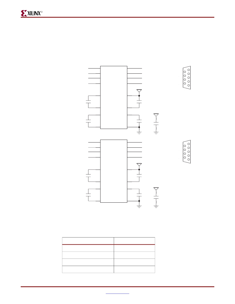
RS-232 Ports
Two RS-232 ports, shown in Figure 2-10 , are connected to the FPGA (U37) through
independent MAX3232 transceivers (U7 and U46). The FPGA RS-232 ports are wired as
DTE and meet the EIA/TIA-574 standard. The ports are accessible via two DB9M
connectors integrated on the P1 connector assembly.
From FPGA
U7
S eri a l Port A
UART0_TXD
UART0_RT S _N
UART0_RXD
UART0_CT S _N
11
10
12
9
DIN1
DIN2
ROUT1
ROUT2
DOUT1 14
DOUT2 7
RIN1 1 3
RIN2 8
COM0_TXD_N
COM0_RT S
COM0_RXD_N
COM0_CT S
D S R 6
RT S 7
CT S 8
RI 9
1 CD
2 RX
3 TX
4 DTR
5 GND
VCC 3 V 3
C 33 0
0.1UF
1
C1+
VCC 16
C 3 26
0.1UF
R S -2 3 2 DTE pino u t connect s
to PC with F/F n u ll modem c ab le.
3
C1-
V+
2
4
C2+
V-
6
VCC 3 V 3
C 33 1
C 3 27
0.1UF
0.1UF
C 3 1 3
0.1UF
From FPGA
5
C2-
MAX 3 2 3 2
U46
GND 15
S eri a l Port B
UART1_TXD
UART1_RT S _N
UART1_RXD
UART1_CT S _N
11
10
12
9
DIN1
DIN2
ROUT1
ROUT2
DOUT1 14
DOUT2 7
RIN1 1 3
RIN2 8
COM1_TXD_N
COM1_RT S
COM1_RXD_N
COM1_CT S
D S R 6
RT S 7
CT S 8
RI 9
1 CD
2 RX
3 TX
4 DTR
5 GND
VCC 3 V 3
C 33 0
0.1UF
1
C1+
VCC 16
C 3 26
0.1UF
R S -2 3 2 DTE pino u t connect s
to PC with F/F n u ll modem c ab le.
3
C1-
V+
2
4
C2+
V-
6
VCC 3 V 3
C 33 1
C 3 27
0.1UF
0.1UF
C 3 1 3
0.1UF
5
C2-
GND 15
MAX 3 2 3 2
Figure 2-10:
FPGA UART and RS-232 Connectivity
UG0 8 5_10_120605
and UART1.
Table 2-12:
FPGA RS-232 Connections for UART0
Signal Name
UART0_CTS_N
UART0_RTS_N
UART0_RXD
UART0_TXD
FPGA Pin (U37)
G6
F6
E6
D6
ML410 Embedded Development Platform
UG085 (v1.7.2) December 11, 2008
43
发布紧急采购,3分钟左右您将得到回复。
相关PDF资料
HW-V5-ML501-UNI-G
EVALUATION PLATFORM VIRTEX-5
HW-V5-ML507-UNI-G
EVAL PLATFORM V5 FXT
HW-V5-ML550-UNI-G
EVALUATION PLATFORM VIRTEX-5
HW-V5-ML555-G
BOARD EVAL FOR VIRTEX-5 ML555
HW-V5-ML561-UNI-G
EVALUATION PLATFORM VIRTEX-5
I-JET
JTAG ARM DEBUGGING PROBE
IAC24A
INPUT MODULE AC 5MA 24VDC
IAC5EQ
INPUT MODULE AC 10MA 5VDC
相关代理商/技术参数
HW-V4-ML423-UNI-G
功能描述:EVALUATION PLATFORM VIRTEX-4 RoHS:是 类别:编程器,开发系统 >> 过时/停产零件编号 系列:Virtex®-4 标准包装:1 系列:- 传感器类型:CMOS 成像,彩色(RGB) 传感范围:WVGA 接口:I²C 灵敏度:60 fps 电源电压:5.7 V ~ 6.3 V 嵌入式:否 已供物品:成像器板 已用 IC / 零件:KAC-00401 相关产品:4H2099-ND - SENSOR IMAGE WVGA COLOR 48-PQFP4H2094-ND - SENSOR IMAGE WVGA MONO 48-PQFP
HW-V4-ML423-UNI-G-J
功能描述:EVALUATION PLATFORM VIRTEX-4 RoHS:是 类别:编程器,开发系统 >> 通用嵌入式开发板和套件(MCU、DSP、FPGA、CPLD等) 系列:Virtex®-4 产品培训模块:Blackfin® Processor Core Architecture Overview
Blackfin® Device Drivers
Blackfin® Optimizations for Performance and Power Consumption
Blackfin® System Services 特色产品:Blackfin? BF50x Series Processors 标准包装:1 系列:Blackfin® 类型:DSP 适用于相关产品:ADSP-BF548 所含物品:板,软件,4x4 键盘,光学拨轮,QVGA 触摸屏 LCD 和 40G 硬盘 配用:ADZS-BFBLUET-EZEXT-ND - EZ-EXTENDER DAUGHTERBOARDADZS-BFLLCD-EZEXT-ND - BOARD EXT LANDSCAP LCD INTERFACE 相关产品:ADSP-BF542BBCZ-4A-ND - IC DSP 16BIT 400MHZ 400CSBGAADSP-BF544MBBCZ-5M-ND - IC DSP 16BIT 533MHZ MDDR 400CBGAADSP-BF542MBBCZ-5M-ND - IC DSP 16BIT 533MHZ MDDR 400CBGAADSP-BF542KBCZ-6A-ND - IC DSP 16BIT 600MHZ 400CSBGAADSP-BF547MBBCZ-5M-ND - IC DSP 16BIT 533MHZ MDDR 400CBGAADSP-BF548BBCZ-5A-ND - IC DSP 16BIT 533MHZ 400CSBGAADSP-BF547BBCZ-5A-ND - IC DSP 16BIT 533MHZ 400CSBGAADSP-BF544BBCZ-5A-ND - IC DSP 16BIT 533MHZ 400CSBGAADSP-BF542BBCZ-5A-ND - IC DSP 16BIT 533MHZ 400CSBGA
HW-V4SX35-VIDEO-SK-EC
功能描述:VIRTEX-4 VIDEO STARTER KIT RoHS:否 类别:编程器,开发系统 >> 过时/停产零件编号 系列:Virtex®-4 标准包装:1 系列:- 传感器类型:CMOS 成像,彩色(RGB) 传感范围:WVGA 接口:I²C 灵敏度:60 fps 电源电压:5.7 V ~ 6.3 V 嵌入式:否 已供物品:成像器板 已用 IC / 零件:KAC-00401 相关产品:4H2099-ND - SENSOR IMAGE WVGA COLOR 48-PQFP4H2094-ND - SENSOR IMAGE WVGA MONO 48-PQFP
HW-V4SX35-VIDEO-SK-UK
功能描述:VIRTEX-4 VIDEO STARTER KIT RoHS:否 类别:编程器,开发系统 >> 过时/停产零件编号 系列:Virtex®-4 标准包装:1 系列:- 传感器类型:CMOS 成像,彩色(RGB) 传感范围:WVGA 接口:I²C 灵敏度:60 fps 电源电压:5.7 V ~ 6.3 V 嵌入式:否 已供物品:成像器板 已用 IC / 零件:KAC-00401 相关产品:4H2099-ND - SENSOR IMAGE WVGA COLOR 48-PQFP4H2094-ND - SENSOR IMAGE WVGA MONO 48-PQFP
HW-V5GBE-DK-UNI-G
功能描述:KIT DEV V5 LXT GIGABIT ETHERNET RoHS:是 类别:编程器,开发系统 >> 通用嵌入式开发板和套件(MCU、DSP、FPGA、CPLD等) 系列:Virtex®-5 LXT 产品培训模块:Blackfin® Processor Core Architecture Overview
Blackfin® Device Drivers
Blackfin® Optimizations for Performance and Power Consumption
Blackfin® System Services 特色产品:Blackfin? BF50x Series Processors 标准包装:1 系列:Blackfin® 类型:DSP 适用于相关产品:ADSP-BF548 所含物品:板,软件,4x4 键盘,光学拨轮,QVGA 触摸屏 LCD 和 40G 硬盘 配用:ADZS-BFBLUET-EZEXT-ND - EZ-EXTENDER DAUGHTERBOARDADZS-BFLLCD-EZEXT-ND - BOARD EXT LANDSCAP LCD INTERFACE 相关产品:ADSP-BF542BBCZ-4A-ND - IC DSP 16BIT 400MHZ 400CSBGAADSP-BF544MBBCZ-5M-ND - IC DSP 16BIT 533MHZ MDDR 400CBGAADSP-BF542MBBCZ-5M-ND - IC DSP 16BIT 533MHZ MDDR 400CBGAADSP-BF542KBCZ-6A-ND - IC DSP 16BIT 600MHZ 400CSBGAADSP-BF547MBBCZ-5M-ND - IC DSP 16BIT 533MHZ MDDR 400CBGAADSP-BF548BBCZ-5A-ND - IC DSP 16BIT 533MHZ 400CSBGAADSP-BF547BBCZ-5A-ND - IC DSP 16BIT 533MHZ 400CSBGAADSP-BF544BBCZ-5A-ND - IC DSP 16BIT 533MHZ 400CSBGAADSP-BF542BBCZ-5A-ND - IC DSP 16BIT 533MHZ 400CSBGA
HW-V5GBE-DK-UNI-G-J
功能描述:KIT DEV GIGABIT ETHERNET VIRTEX5 RoHS:是 类别:编程器,开发系统 >> 通用嵌入式开发板和套件(MCU、DSP、FPGA、CPLD等) 系列:Virtex®-5 LXT 产品培训模块:Blackfin® Processor Core Architecture Overview
Blackfin® Device Drivers
Blackfin® Optimizations for Performance and Power Consumption
Blackfin® System Services 特色产品:Blackfin? BF50x Series Processors 标准包装:1 系列:Blackfin® 类型:DSP 适用于相关产品:ADSP-BF548 所含物品:板,软件,4x4 键盘,光学拨轮,QVGA 触摸屏 LCD 和 40G 硬盘 配用:ADZS-BFBLUET-EZEXT-ND - EZ-EXTENDER DAUGHTERBOARDADZS-BFLLCD-EZEXT-ND - BOARD EXT LANDSCAP LCD INTERFACE 相关产品:ADSP-BF542BBCZ-4A-ND - IC DSP 16BIT 400MHZ 400CSBGAADSP-BF544MBBCZ-5M-ND - IC DSP 16BIT 533MHZ MDDR 400CBGAADSP-BF542MBBCZ-5M-ND - IC DSP 16BIT 533MHZ MDDR 400CBGAADSP-BF542KBCZ-6A-ND - IC DSP 16BIT 600MHZ 400CSBGAADSP-BF547MBBCZ-5M-ND - IC DSP 16BIT 533MHZ MDDR 400CBGAADSP-BF548BBCZ-5A-ND - IC DSP 16BIT 533MHZ 400CSBGAADSP-BF547BBCZ-5A-ND - IC DSP 16BIT 533MHZ 400CSBGAADSP-BF544BBCZ-5A-ND - IC DSP 16BIT 533MHZ 400CSBGAADSP-BF542BBCZ-5A-ND - IC DSP 16BIT 533MHZ 400CSBGA
HW-V5GBE-DK-UNI-G-PROMO1
功能描述:KIT DEV V5 LXT GIGABIT ETHERNET RoHS:是 类别:编程器,开发系统 >> 过时/停产零件编号 系列:- 标准包装:1 系列:- 传感器类型:CMOS 成像,彩色(RGB) 传感范围:WVGA 接口:I²C 灵敏度:60 fps 电源电压:5.7 V ~ 6.3 V 嵌入式:否 已供物品:成像器板 已用 IC / 零件:KAC-00401 相关产品:4H2099-ND - SENSOR IMAGE WVGA COLOR 48-PQFP4H2094-ND - SENSOR IMAGE WVGA MONO 48-PQFP
HW-V5GBE-DK-UNI-G-PROMO2
功能描述:KIT DEV V5 LXT GIGABIT ETHERNET RoHS:是 类别:编程器,开发系统 >> 过时/停产零件编号 系列:Virtex® 标准包装:1 系列:- 传感器类型:CMOS 成像,彩色(RGB) 传感范围:WVGA 接口:I²C 灵敏度:60 fps 电源电压:5.7 V ~ 6.3 V 嵌入式:否 已供物品:成像器板 已用 IC / 零件:KAC-00401 相关产品:4H2099-ND - SENSOR IMAGE WVGA COLOR 48-PQFP4H2094-ND - SENSOR IMAGE WVGA MONO 48-PQFP
